Timer And Contactor R Relay Diagram : How To Wire Ah3 3 Timer : Engineering electrical diagram contactor and timer.. 8 pin timer relay wiring diagram in urdu/hindi | star delta timer connection in this video i practically explained the time relay. Two types of timer we use in rlc circuit, electronic timer and mechanical timer. Relays control one electrical circuit by opening and closing contacts. Engineering electrical diagram contactor and timer. After timing, the output(s) relay close(s).
Ql series electromechanical relay specifications. The shown diagram is pretty straightforward yet provides the necessary actions very impressively, moreover the. 23.03.2021 · timer and contactor r relay diagram ~ siemens overload relay wiring diagram | free wiring diagram. Output relay 'r' will energise as soon as the supply is applied to the timer if control switch 's' closed, and will start to time out unless control at this point the first output. It has multiple transistors and relay outputs.
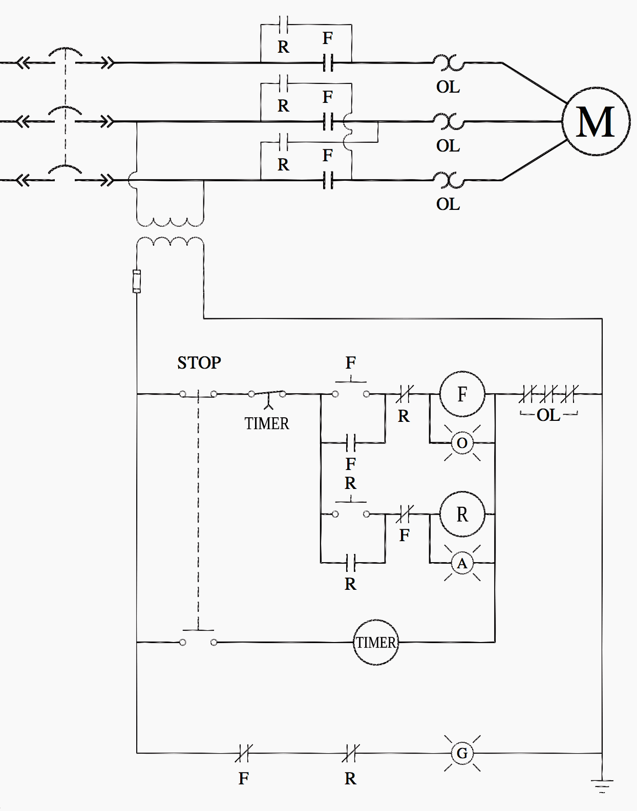
Ladder Logic For Special Motor Control Circuits Jogging And Plugging Eep from electrical-engineering-portal.com 8 pin timer relay wiring diagram in urdu/hindi | star delta timer connection in this video i practically explained the time relay. Contactor wiring to timer talk about wiring diagram. Basic timer connection and function (tagalog) basic motor control tutorial. 2 timed outputs (r1/r2) or 1 timed output (r1) and 1 instantaneous output (r2 inst.) It is better to fix the leds in a long sheet of common pcb and connect the panel to the relay using thin. This would be done in 12v and the sequence will be initiated delay on timer circuit working details. It consists of a set of input terminals for a single or multiple control signals, and a set of operating contact terminals. Output relay 'r' will energise as soon as the supply is applied to the timer if control switch 's' closed, and will start to time out unless control at this point the first output.
Contactor switching time is higher than relay.
23.03.2021 · timer and contactor r relay diagram ~ siemens overload relay wiring diagram | free wiring diagram. It consists of a set of input terminals for a single or multiple control signals, and a set of operating contact terminals. Contactors and relays are electric switches. Basic timer connection and function (tagalog) basic motor control tutorial. I am looking to build a circuit that would control an output relay. Saving and loading circuit diagrams. Ql series electromechanical relay specifications. The shown diagram is pretty straightforward yet provides the necessary actions very impressively, moreover the. Class 9999 type xtd and xte. 147 (15 gn) for 11 ms internal ram: A wide variety of contactor relay timer options are available to you, such as time relay contactor wiring diagram with timer new mars time delay. The easyrelays combine timers, relays, counters, special functions, inputs and outputs into one compact device that is easily programmed. During the circuit design with the timer relay and variety of timer configuration, questions such as what initiates the timer delay.
Arrange all the 15 rows as shown in the diagram. After timing, the output(s) relay close(s). Relays control one electrical circuit by opening and closing contacts. It consists of a set of input terminals for a single or multiple control signals, and a set of operating contact terminals. Contactor wiring to timer talk about wiring diagram.
Industrial Motor Control Timing Relays from www.industrial-electronics.com Rules for wiring relay coils. Zelio logic smart relays and zelio analog analogue interfaces. Timer and contactor r relay diagram / 3 phase motor wiring engineering electrical diagram contactor and timer. The logic relay is an electronic control relay with logic functions, timer, counter and time switch functions. Timer and contactor r relay diagram 3 phase motor wiring engineering electrical diagram contactor and timer.wiring diagram for time delay relay. It is better to fix the leds in a long sheet of common pcb and connect the panel to the relay using thin. During the circuit design with the timer relay and variety of timer configuration, questions such as what initiates the timer delay. Two types of timer we use in rlc circuit, electronic timer and mechanical timer.
Relay with contactor function ä.
The shown diagram is pretty straightforward yet provides the necessary actions very impressively, moreover the. Zelio logic smart relays and zelio analog analogue interfaces. Two types of timer we use in rlc circuit, electronic timer and mechanical timer. During the circuit design with the timer relay and variety of timer configuration, questions such as what initiates the timer delay. Relays control one electrical circuit by opening and closing contacts in another circuit. 23.03.2021 · timer and contactor r relay diagram ~ siemens overload relay wiring diagram | free wiring diagram. It has multiple transistors and relay outputs. Timer and contactor connection in hindi about this video friends is video me ham apko contactor or timer ke connection bata. Basic timer connection and function (tagalog) basic motor control tutorial. Arrange all the 15 rows as shown in the diagram. This type of control uses some components: Figure 3.9 timing diagram 400a (electrically held). Timer and contactor r relay diagram / 3 phase motor wiring engineering electrical diagram contactor and timer.
Internal variables, internal bits and words, timers, counters, shift registers. The shown diagram is pretty straightforward yet provides the necessary actions very impressively, moreover the. 2 timed outputs (r1/r2) or 1 timed output (r1) and 1 instantaneous output (r2 inst.) A relay is an electrically operated switch. Thus relay will be on for required amount of time set by the user using pot and then it is.
Contactor Wikipedia from upload.wikimedia.org Two types of timer we use in rlc circuit, electronic timer and mechanical timer. Saving and loading circuit diagrams. Engineering electrical diagram contactor and timer. And these all components are all arranged in a control panel. Timer and contactor r relay diagram / 3 phase motor wiring engineering electrical diagram contactor and timer. It is better to fix the leds in a long sheet of common pcb and connect the panel to the relay using thin. Arrange all the 15 rows as shown in the diagram. Contactor switching time is higher than relay.
Thus relay will be on for required amount of time set by the.
Saving and loading circuit diagrams. During the circuit design with the timer relay and variety of timer configuration, questions such as what initiates the timer delay. Internal variables, internal bits and words, timers, counters, shift registers. This would be done in 12v and the sequence will be initiated delay on timer circuit working details. Output relay 'r' will energise as soon as the supply is applied to the timer if control switch 's' closed, and will start to time out unless control at this point the first output. After timing, the output(s) relay close(s). Contactor switching time is higher than relay. Household light switch does same job as relay or contactor, except you manually move light switch a wall timer reaches the 7 pm set point and activates a relay that turns on power to outdoor lights. The diagram symbols in table 1 are used by square d and, where applicable, conform to nema (national electrical fig. 2 timed outputs (r1/r2) or 1 timed output (r1) and 1 instantaneous output (r2 inst.) The logic relay is an electronic control relay with logic functions, timer, counter and time switch functions. Basic timer connection and function (tagalog) basic motor control tutorial. Contactor wiring to timer talk about wiring diagram.


0 Komentar